Copyright © 2004-2005, 2007 Thomas M. Eastep
Permission is granted to copy, distribute and/or mify this document under the terms of the GNU Free Documentation License, Version 1.2 or any later version published by the Free Software Foundation; with no Invariant Sections, with no Front-Cover, and with no Back-Cover Texts. A copy of the license is included in the section entitled “GNU Free Documentation License”.
2007/07/19
Table of Contents
Network Mapping is most often used to resolve IP address conflicts. Suppose that two organizations, A and B, need to be linked and that both organizations have allocated the 192.168.1.0/24 subnetwork. There is a need to connect the two networks so that all systems in A can access the 192.168.1.0/24 network in B and vice versa without any re-addressing.
Shorewall NETMAP support is designed to supply a solution. The basic situation is as shown in the following diagram.
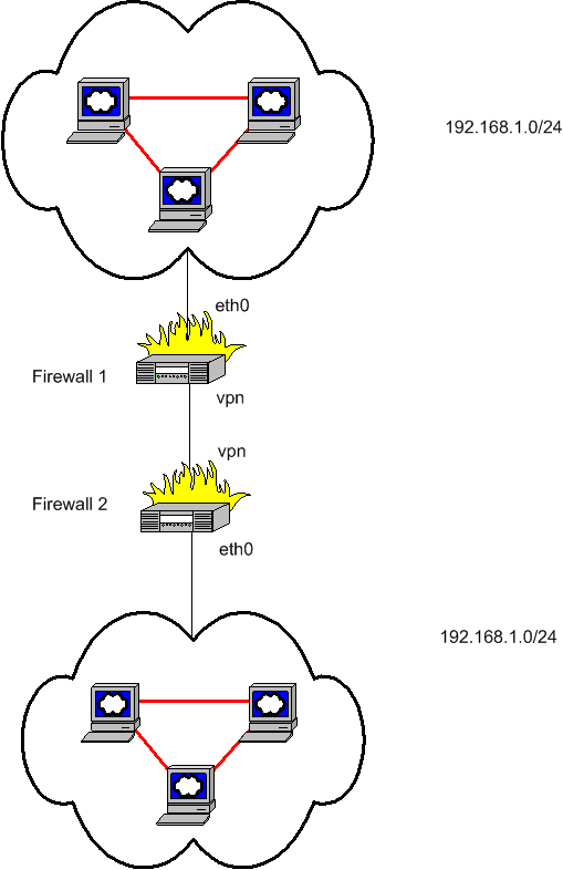
While the link between the two firewalls is shown here as a VPN, it could be any type of interconnection that allows routing of RFC 1918 traffic.
The systems in the top cloud will access the 192.168.1.0/24 subnet in the lower cloud using addresses in another unused /24. Similarly, the systems in the bottom cloud will access the 192.168.1.0/24 subnet in the upper cloud using a second unused /24.
In order to apply this solution:
You must be running Shorewall 2.0.1 Beta 2 or later.
Your kernel must have NETMAP support. 2.6 Kernels have NETMAP support without patching while 2.4 kernels must be patched using Patch-O-Matic from netfilter.org.
NETMAP support must be enabled in your kernel (CONFIG_IP_NF_TARGET_NETMAP=m or CONFIG_IP_NF_TARGET_NETMAP=y).
Your iptables must have NETMAP support. NETMAP support is available in iptables 1.2.9 and later.
Network mapping is defined using the
/etc/shorewall/netmap file. Columns in this file
are:
- TYPE
Must be DNAT or SNAT.
If DNAT, traffic entering INTERFACE and addressed to NET1 has its destination address rewritten to the corresponding address in NET2.
If SNAT, traffic leaving INTERFACE with a source address in NET1 has its source address rewritten to the corresponding address in NET2.
- NET1
Must be expressed in CIDR format (e.g., 192.168.1.0/24).
- INTERFACE
A firewall interface. This interface must have been defined in
/etc/shorewall/interfaces.- NET2
A second network expressed in CIDR format.
Referring to the figure above, lets suppose that systems in the top cloud are going to access the 192.168.1.0/24 network in the bottom cloud using addresses in 10.10.10.0/24 and that systems in the bottom could will access 192.168.1.0/24 in the top could using addresses in 10.10.11.0.
Important
You must arrange for routing as follows:
Traffic from the top cloud to 10.10.10.0/24 must be routed to eth0 on firewall 1.
Firewall 1 must route traffic to 10.10.10.0/24 through firewall 2.
Traffic from the bottom cloud to 10.10.11.0/24 must be routed to eth0 on firewall 2.
Firewall 2 must route traffic to 10.10.11.0/24 through firewall 1.
The entries in
/etc/shorewall/netmap
#TYPE NET1           INTERFACE        NET2
SNAT  192.168.1.0/24 vpn              10.10.11.0/24        #RULE 1A
DNAT  10.10.11.0/24  vpn              192.168.1.0/24       #RULE 1B
The entry in /etc/shorewall/netmap in firewall2
would be:
#TYPE NET1           INTERFACE        NET2
DNAT  10.10.10.0/24  vpn              192.168.1.0/24       #RULE 2A
SNAT  192.168.1.0/24 vpn              10.10.10.0/24        #RULE 2B
Example 1. 192.168.1.4 in the top cloud connects to 192.168.1.27 in the bottom cloud
In order to make this connection, the client attempts a connection
to 10.10.10.27. The following table shows how the source and destination
IP addresses are modified as requests are sent and replies are returned.
The RULE column refers to the above
/etc/shorewall/netmap entries and gives the rule
which transforms the source and destination IP addresses to those shown
on the next line.
| FROM | TO | SOURCE IP ADDRESS | DESTINATION IP ADDRESS | RULE |
|---|---|---|---|---|
| 192.168.1.4 in upper cloud | Firewall 1 | 192.168.1.4 | 10.10.10.27 | 1A |
| Firewall 1 | Firewall 2 | 10.10.11.4 | 10.10.10.27 | 2A |
| Filrewall 2 | 192.168.1.27 in lower cloud | 10.10.11.4 | 192.168.1.27 | |
| 192.168.1.27 in the lower cloud | Firewall 2 | 192.168.1.27 | 10.10.11.4 | 2B |
| Firewall 2 | Firewall 1 | 10.10.10.27 | 10.10.11.4 | 1B |
| Firewall 1 | 192.168.1.4 in upper cloud | 10.10.10.27 | 192.168.1.4 |
This could all be made a bit simpler by eliminating the TYPE field and have Shorewall generate both the SNAT and DNAT rules from a single entry. I have chosen to include the TYPE in order to make the implementation a bit more flexible. If you find cases where you can use an SNAT or DNAT entry by itself, please let me know and I'll add the example to this page.
In the previous section, the table in the example contains a bit of a lie. Because of Netfilter's connection tracking, rules 2B and 1B aren't needed to handle the replies. They ARE needed though for hosts in the bottom cloud to be able to establish connections with the 192.168.1.0/24 network in the top cloud.
I wrote this article before Shorewall included multiple provider support. You should be able to accomplish the same thing with just one router through careful use of /etc/shorewall/netmap and multiple providers. If you try it and get it working, please contribute an update to this article.